Turnkey solution simplifies power design task for railway industry
Cincon has launched an ultra-wide turnkey solution that can accelerate system designers’ development phase for railway applications because of its highly functional integration

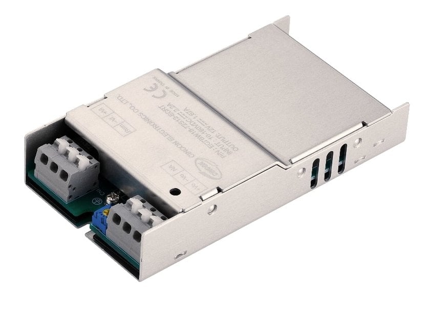
Cincon’s EC7BW18-ECRT/EDRT turnkey solution is feature-packed for railway sector applications.
How to efficiently incorporate the power module into rail systems has received much attention from power manufacturers and engineers. In railway applications, the power module as a drive to start up the control system plays a crucial role in the control system. However, it is not an easy task to connect it into the railway system because each circuit module for onboard equipment is intricated. Besides, the rail track voltage parameters might vary across the areas. Moreover, the power converter in the rail application should be rugged enough against the unexpected situations, resulting from the train-borne operation exposed to a long-term stringent environment. In this respect, it is essential for a power converter to be approved by EN 50155, EN 61373, and EN 45545-2 standards. EN 50155 standard, as shown in Table 1, sets the parameters that a power converter should withstand the fluctuation voltage and supports distributed voltages of 24 VDC, 36 VDC, 48 VDC, 72 VDC, 96 VDC, and 110 VDC.

Table 1: EN 50155 input voltage range
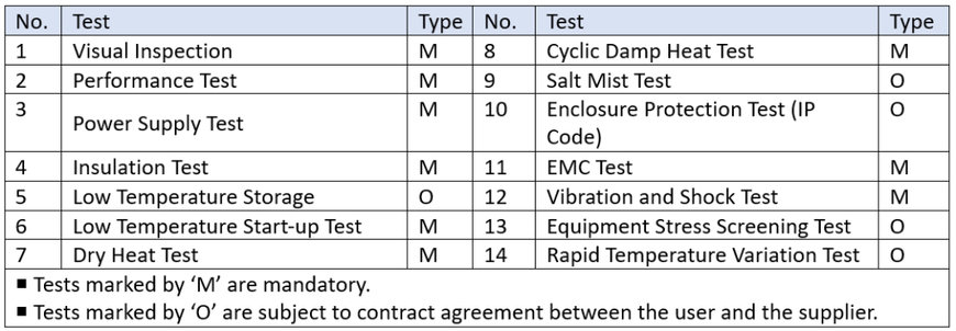
Table 2 shows a European EN 50155 railway standard. The parameters have multiple electrical aspects set for a power converter to ensure its adaptability to various environmental factors, such as vibration, shock, and temperature. The EC7BW18-ECRT/EDRT DC/DC converter module from Cincon Electronics Co., Ltd., as an example, can meet this expectation. This series has been certified for the related environments to confirm its capability and performance.

Table 2: EN 50155 tests
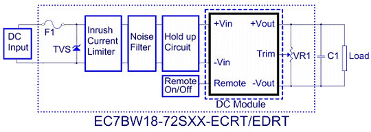
The series is available in chassis-mount or chassis-mount with DIN-rail choices, offering ultra-wide input voltages of 10 VDC to 160 VDC. In addition to the internal DC module itself, as shown in Figure 1, this turnkey solution has key components such as a hold-up circuit, noise filter, and inrush current limiter.

Figure 1: Block diagram of the EC7BW18-ECRT/EDRT
How does a turnkey solution facilitate power design?
System designers will face some of the most complex challenges, such as electromagnetic interference (EMI), hold-up time, and inrush current issues when connecting the power module to the control system by external circuitry. Since this turnkey converter features the built-in components─inrush current limiter, noise filter, and hold-up circuit, it allows system designers to save time and effort on the workflow of wiring layout by merely ensuring if the power module can be successfully operated on the rail instrument after installation. This turnkey converter cannot merely reduce bill-of-material costs, but also simplify maintenance of equipment because of the modular power converter. It indeed shortens the development design phase of system engineers.
Inrush Current Limiter
It is pivotal for the DC/DC power converter to have an additional capacitor in the input side during the load transients, while the capacitor might pose the higher inrush current problem at the input side. If there is no action in reducing the inrush current, it will likely raise a voltage drop and even over-current protection in the front-end power supply, ultimately resulting in no output from the converter.
The EC7BW18-ECRT/EDRT series features a built-in active inrush limiter to address this problem. The active inrush limiter offers higher efficiency and is less influenced by the ambient temperature. The below graphs indicate, by the same input voltage of 36 VDC, the two sets of EC7BW18-72S05-ECRT have the different results of the inrush current separately. Figure 2 is 3.12A (with an active inrush current limiter), while Figure 3 is 27.6A (without an inrush current limiter). If the input voltage becomes higher, their data difference of inrush current will be more evident.

Figure 2 (left) with an inrush current limiter and Figure 3 (right) without an inrush current limiter. Notes: CH1 is the input voltage, CH2 is the input current, and CH3 is the output voltage.
Hold up Circuit
The railway power system is influenced by switching between generator, battery, and pantograph, a result which the conspicuous fluctuations of supply voltage might have in a short period. This may lead to a short-term open circuit or short circuit. Based on interruptions of voltage supply and supply change-over, the EN 50155 power test is divided into different performance classes:
Interruptions of Voltage Supply:
- Class S1: No voltage interruption. No performance criterion is requested, but the equipment shall continue to operate as specified after the voltage interruption.
- Class S2: Interruption time of 10 ms, performance criterion A
- Class S3: Interruption time of 20 ms, performance criterion A
Supply Change-over:
- Class C1: At 0.6* Vin during 100 ms (without interruptions). Performance criterion A
- Class C2: During a supply break of 30 ms stating at Vin. Performance criterion B
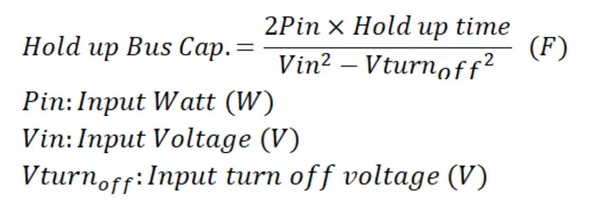
It is important to add capacitors in the input side of the DC/DC converter according to the requirements of S2, S3, and C2. The capacitance value can be analyzed through the below formula. Based on the same hold-up time, the formula discloses that the lower voltage inputs, the higher capacitance value requires.

The EC7BW18-ECRT/EDRT employs a built-in hold-up circuit that meets the requirements of S2, S3, and C2. The pictures below show that the hold-up time figures between two sets of EC7BW18-72S05-ECRT, with and without the hold-up circuit. Although they both have the same input voltage of 24 VDC, the hold-up time for the test with a built-in hold up circuit is 13 ms (Figure 4) in comparison with 0.88 ms without hold-up circuit (Figure 5).

Figure 4 (left) with a hold-up circuit and Figure 5 (right) without a hold-up circuit.
Notes: CH1 is the input voltage and CH2 is the output voltage.
Conclusion
Over the past decades, modern rail industry has a great step forward with the advent of the digital age. The rail on-board apparatus has become more numerous and advanced with a view to offering a comfortable environment for passengers. However, the space constraints on equipment have become a thorny problem. Module integration is thus important. The feature-rich power converter, as an example, packs more functionality that benefits system designers to shorten the development phase and make good use of mechanical spatial layout of equipment.
With the built-in EMI protection, inrush current limiter, and hold-up circuitry, the turnkey solution approved by the EN 50155 railway standard offers an ultra-wide input voltage range of 10 VDC to 160 VDC, accessible to all types of voltage parameters in different areas. This 16:1 input DC/DC turnkey converter can be used for onboard electronic apparatus since it is equipped with the adaptability to withstand the voltage fluctuation of the instruments. For system safety consideration, the hold-up circuit, included in this converter solution, serves as a cushion during emergencies in case there is no input voltage. Simultaneously, an EMI filter used in this module can minimize an adequate level of radiated emission and provide protection against interference from electrical and electronic devices on railway rolling stock.
www.cincon.com

