
railway-international.com
12
'23
Written on Modified on
The new Storstrøm Bridge ; a 3.832 km road and railway link
The new Storstrøm Bridge is a 3.832 km road and railway link crossing the Storstrøm channel between Falster and Masnedø.
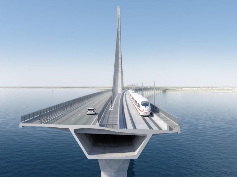
Two approach viaducts that are 80m long with 44 spans.
A central cable-stayed bridge.
44 prefabricated foundations and piers.
Two abutments.
Temporary steel structures.
Approach embankments and underpass structures
In Denmark, the new 4km long Storstrøm Bridge between Masnedø amd Flaster will replace the existing from 1937, which does not have the capacity to carry the increased railway freight traffic resulting from the future opening of the Fehmarn Belt Connection.
The Design and Build Contract was awarded in February 2018, at the end of a Competitive Dialogue process carried out by Danish Road Directorate. The Illustrative Design was issued by DRD as basis for the Tender phase and was then developed by Studio de Miranda Associati (DMA), together with Geo ltd and Seteco srl for the foundations, and EKJ for Landworks, as Structural Consultant for the JV formed by the Italian contractors Itinera, Condotte d’Acqua, and GLF. After the award of the Project by the JV, the Design continued, carried out by DMA for the main bridge, in partnership with SGI for geotechnics.
This was followed by a detailed design of the prototype structures, which are the abutments, typical foundations and piers, cast-in-place girders, pre-cast girders and pylon foundation, which were also checked and approved, completing the fundamental design of the bridge. DMA then accompanied the early phases of construction. After four years of design work, the baton was then passed on to Ramboll Consultants for completion and detailing.
Design philosophy
The design of the structure and the conception of the construction methods are tightly linked in large bridges.
When De Miranda Associati began working on the design of the new Storstrøm Bridge, there were five main challenges to be faced and solved.
Logistics, weather, and quality all considered the target of high concrete quality and great durability calls for fabrication under the best possible conditions; optimal conditions require a properly sheltered, equipped and conditioned workshop.
Optimizing the cost-benefit ratio requires an economy of scale, meaning standardization of construction procedures and concentration of production plants.
There was a tight schedule for bridge construction and the goal of economizing by reducing indirect costs proportionate to construction time required an industrialized construction system and innovative erection methods.
Analysis of the possible options for responding to these challenges led to the elimination of traditional cast-in-place solutions such as those involving travelling formworks, with all the construction performed offshore, involving the transportation of materials and workers over long distances.
The option of using precast segments for the deck, with many construction joints, was also rejected, as was longitudinal launching, because of the risks and difficulties involved in the planned curvature of the deck girder, the double curvature in elevation, and the very significant lengths and weights to be displaced.
Instead, the real answers to the challenges were found through the implementation of five key solver concepts:
Prefabrication: to build the concrete elements under the best possible environmental conditions, allowing and incentivizing better quality, and minimizing offshore workers’ activities.
Full prefabrication: meaning precasting of foundations, piers and girders, to concentrate all production work in a single optimally equipped area and obtain the maximum advantages for economies of scale.
Large-scale prefabrication: meaning precasting and erecting of full-length girders, thereby minimizing transport, lifting and joining operations.
Design of special methods and equipment permitting rapid erection using specially designed structures and standard nautical/lifting equipment. This avoids the need to use mega-cranes, which are difficult to find and expensive, potentially conflicting with the efficiency of the work.
Integration: meaning adoption of the same construction method for the viaducts and for the cable-stayed bridge, taking full advantage of the same construction plant, the training of work teams that have already taken place, and the same erection equipment. Integration also means a tight combination of design with the construction concepts and plans, from the beginning of the conception phase.
Structural concepts
The bridge is composed of a main bridge and two approach viaducts, all constructed out of reinforced, prestressed concrete.
The main bridge is a cable-stayed bridge with two spans of 160m.
The whole structure is segmented into three sections, North, Central, and South, divided by two expansion joints and linked by shock transmission units.
At all locations other than the longitudinal fixed links, there is one unidirectional and one multidirectional bearing. Shear keys are provided in the piers with the highest horizontal loads in the event of impact by a ship.
The deck girder has the following features and structural behaviour:
Shape: trapezoidal box girder, with cantilevered sides in solid slab construction with variable thickness of webs and bottom slab; longitudinally prestressed.
Height: Total structural depth is 5.623m, apart from a short portion near the North abutment which is reduced to 5.312m.
The top slab is on two levels, as requested by the Client, connected at the centre by a longitudinal beam with side cantilevers in solid slab construction of variable thickness.
The foundations are designed as direct foundations resting on a gravel bed base and have a structure of caissons of variable dimensions as appropriate to the different soil conditions, prefabricated, loaded out and installed by a catamaran.
The piers have a shape of variable geometry, changing from rectangular to hexagonal sections with both transverse and longitudinal variability with height, as requested by the Client.
This high variability could hardly be managed with a cast-in-place construction, which is why construction in prefabricated segments was planned.
Construction Methods
All the structures are prefabricated apart from the first two spans, close to both abutments, which were to be built during the completion of the prefabrication plant and the cable-stayed tower, the singularity of which discouraged the use of precasting.
Construction method of viaducts:
Foundations are caissons, precast in a specific workshop, loaded onto a barge and then placed on a gravel pad, laying them over appropriate subsoil, typically over consolidated clay tills. According to a De Miranda procedure, the foundations are put in place by a catamaran, which lifts the element from the barge, allows the barge to move back, centres the element in its theoretical position with horizontal hydraulic aligners and then lowers it onto the gravel pad using a strand jacking system.
Piers are erected by an original system, also designed by De Miranda, which consists of the assembly of precast segments connected by special embedded steel frames which allow level and tilt adjustment by shimming, permitting very quick dry installation.
Pier segments are positioned using 600t capacity pontoons.
After completing the full erection of the pier segments, the concrete joints are poured in sequence, then the top-pier-deck segment is also installed.
Deck girders are prefabricated in a workshop organized in a five-step production line.
Following post-tensioning and loadout onto the barge, the girder is shipped to the erection site and lifted by a special system of movable lifting arms and lifting towers designed by De Miranda, centred on piers, without cantilevers. This induces vertical loads only on the pier tops.
Cable-stayed bridge construction method:
The cable-stayed deck is erected in the same way as the viaducts, allowing it to benefit from the prefabrication plant and equipment used for the viaducts, following the installation of a couple of steel temporary piers at the midspan of the two cable stayed spans.
Following girder erection, the installation and tensioning of the stay cables will take place, allowing removal of the temporary piers when complete.
Pylon foundation:
The construction of the central cable-stayed bridge foresaw the design of special ancillary temporary structures permitting extension of the full prefabrication concept previously presented.
The foundation of Pylon 1C is a precast element to be sailed and sunk, composed of its 34x42x10m plinth and the external portion of the pylon shaft 12.70m high, weighing 11.600t, and creates a safe shaft for the subsequent construction activities following placement in its final position. The detailed design of this element was approved in May 2020, the first casting occurred in October 2020, and the structure was loaded out, sailed, moored, sunk and placed on the seabed in October 2021.
Over the F1C the SSS – Steel Supporting Structure, 950t in weight, the 45m-long in-situ portion of CSB girder at the pylon is erected with the function of scaffolding and supporting the equipment involved in the lifting of lateral precast spans, 60.8m long and 36.8MN each.
Conclusions
Numerous design challenges related to road and railway dynamic actions, wind, ship impact and construction have been faced and solved in the project.
The construction method and structural system illustrated here aimed to allow and integrate the concepts of construction quality, homogeneity, economy and speed.
This is made possible by the integration of structural concepts and construction concepts from the beginning of the design stage.
www.premierconstructionnews.com
